Clustered shading
Introduction
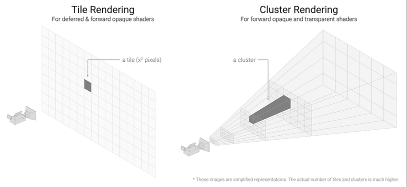
I've always been fascinated with realistic graphics. I believe everyone admires the level of detail in AAA games and I do too. However, it is expensive for the computer to execute those kinds of calculations 60 times per second. While implementing all the realistic effects into our engine, I realised more and more that they would cause performance issues later down the line, but I didn't know what I could do about it. When researching for a solution, I found mainly two ways of computing lights: tiled and clustered shading.
Tiled shading was introduced in the Battlefield 3 era, therefore the older way of calculating lights. After reading about clustered shading I concluded that it is just an extension of tiled shading without the drawbacks of tiled shading. The biggest upside to clustered was that you could light the transparent objects with the same methods as opaque.
What is clustered shading?
At its core, clustered shading is just a culling data structure with the purpose to discard any unnecessary pixel shader calculation. The data structure consists of a fixed amount of clusters and can be visualized as a 3D grid within a view frustum. Each cluster can be thought of as a collision volume and a storage unit. Usually, the collision volume in each cluster is just an AABB with a min and max position that is translated into the view space. By itself the cluster won't make any of your pixel shader calculations faster, you need to fill it with data to be able to make use of it. This is why I call it a data structure rather than an algorithm.
Usecases for clustered shading:
-
Lit shading for every light type
-
Volumetric sample calculations
-
Decal rendering
-
Shading transparent objects
-
Shadow rendering
Constructing the clusters
The first step in implementing clustered shading is to construct the clusters. There are several different ways to build clusters, it all depends on the use case. Getting the X and Y coordinates are very simple because they're are often resolution based. The part that matters is the Z value of each cluster. This is because we do not want a dense packing of clusters further from the camera's position, but rather larger clusters the farther away from the camera they are. This is because we want smaller clusters closer to the camera so they contain very few lights. I just used the algorithm Ángel Ortiz used in his paper to generate the Z values for each cluster. Keep in mind that when you are generating each Z value, you later need to use the same type of algorithm but in reverse. This is because you need to convert the depth value back to clustered indices.
In my implementation,
-
In the compute shader, I assigned a thread group for each cluster to generate the min and max position for the cluster.
-
I have the clusters min and max position in screen space, next I convert it to view space because we want the collision tests to take place within the view frustum.
-
Then put all of the data into a structured buffer.
To test it, I take the absolute position of each cluster and wrote it to a texture in a pixel shader, you can see the results in the picture. The image is not as clear I wanted it to but we can see that we have clusters on the screen that extends along the Z axis.

Sorting the lights into clusters
This is the part that makes the data structure a culling data structure. The goal of this step is to determine which light source belongs to what cluster by using some simple collision tests. I have three different light types: spotlights, pointlights and arealights. This implies three collision shapes: cone sphere, sphere and hemisphere. Every collision check compares against the clusters AABB to find out if it overlaps. If the light overlaps with the clusters AABB we insert the light into our light grid corresponding to the index of the cluster. I won't go into detail about each collision check.
The order in each pass is executed:
-
Cull all the lights on the CPU side and later send it to the GPU.
-
Dispatch is called with the dimensions of our cluster with the instructions to perform the sorting of lights.
-
Then each thread group iterates over all the active lights that we culled on the CPU. It will perform the dedicated collision check for the light type, to determine if it overlaps with the clusters AABB.
This is demonstrated in the images below, where I colour each depending on how many lights I have stored inside it. The more red a cluster is the more lights it contains.


Performing the light calculations
When running the pixel shader for the light we take these steps:
-
Read from our depth texture and get the current pixel coordinates.
-
Then reverse the generation algorithm with the data we just got.
-
This will return a clustered index that we use to index within our light grid.
-
We iterate over all the lights within the light cell we just got, then perform the light calculations as usual.
This is also why it is so simple to shade transparent objects. All of the lights are already in the GPUs memory and can be used any time you have access to the depth buffer. Later I used the cluster to cull my volumetric calculations, so when path-tracing in the volumetric shader I accessed the clusters lights at the sampled position. This led to more performant volumetric calculations and ties back to the culling data structure part.
Conclusion
Clustered shading was such a learning experience to implement. Learning about how the GPU works with compute shaders and how you can optimize it further. The performance I gained got was diminished because of the many shadow issues (every light source are casting shadows). I got about a 30% performance increase but I believe if I removed all the shadows we would see a much better increase. However, I would like to integrate the shadow calculations into the cluster as well as the decals.


http://www.aortiz.me/2018/12/21/CG.html
https://themaister.net/blog/2020/01/10/clustered-shading-evolution-in-granite/
https://studiofreya.com/3d-math-and-physics/sphere-vs-aabb-collision-detection-test/
http://newq.net/dl/pub/SA2014Practical.pdf
https://simoncoenen.com/blog/programming/graphics/SpotlightCulling